Writing a userland driver for Microdot pHAT
I bought this Micro Dot pHAT from Pimoroni a while ago, but the userland driver/library for it is written in Python. As a result, it's slow, has a ton of dependencies, and is about as lightweight as a beached whale.
So to combat these problems, we're gonna write a simpler alternative in the C programming language.
First off we're gonna write a simple makefile.
echo 'all: mdphat' >makefile
done.
The IC we're gonna be dealing with is the IS31FL3730. Actually, we're gonna be dealing with three of them. Each of the IS31FL3730's control two LTP-305HR dot-matrix displays.
Before we start coding, we should consult the datasheet. (how to read a datasheet)
First off we look for what kind of interface the device uses; in this case it's I2C.
This is great since we're gonna be communicating from userland, and Linux has already set up a i2c device file for us at /dev/i2c-1.
With this device file, we can treat it like any other file (the exception being some special ioctl calls).
int d;

d = open("/dev/i2c-1", O_RDWR);
if (d < 0)
    err(1, "open");
Now that the file is opened, we can use ioctl to set our slave address.
We can't find the address in the datasheet, cause it's settable via the AD(6) pin.
The Microdot pHAT pinout page shows that the addresses used are 0x62, 0x63, and 0x61.
We can confirm this by running the i2cdetect command.
$ i2cdetect -y 1
     0  1  2  3  4  5  6  7  8  9  a  b  c  d  e  f
00:          -- -- -- -- -- -- -- -- -- -- -- -- --
10: -- -- -- -- -- -- -- -- -- -- -- -- -- -- -- --
20: -- -- -- -- -- -- -- -- -- -- -- -- -- -- -- --
30: -- -- -- -- -- -- -- -- -- -- -- -- -- -- -- --
40: -- -- -- -- -- -- -- -- -- -- -- -- -- -- -- --
50: -- -- -- -- -- -- -- -- -- -- -- -- -- -- -- --
60: -- 61 62 63 -- -- -- -- -- -- -- -- -- -- -- --
70: -- -- -- -- -- -- -- --
So to attach to that slave address;
ioctl(d, I2C_SLAVE, 0x61);
If we look at page 9 in the datasheet, we'll find the register table.
| Address | Name | Function | Table | Default |
|---|---|---|---|---|
| 00h | Configuration Register | Set operation mode of IS31FL3730 | 3 | 0000 0000 |
| 01h~0Bh | Matrix 1 Data Register | Store the on or off state of each LED | 4 | 0000 0000 |
| 0Eh~18h | Matrix 2 Data Register | Store the on or off state of each LED | 5 | |
| 0Ch | Update Column Register | Make the Data Register update the data | - | xxxx xxxx |
| 0Dh | Lighting Effect Register | Store the intensity of the control settings | 6 | 0000 0000 |
| 19h | PWM Register | Modulate LED light with 128 different items | 7 | 1000 0000 |
| FFh | Reset Register | Reset all registers to default value | - | xxxx xxxx |
Reading through the table, we get the idea of how the memory in the chip is aligned.
The first thing we'll want to do is to write to the configuration register, but first we should make ourselves a function to set the value of a i2c register.
__u8
i2c_set(__u8 reg, __u8 arg) {
    __u8 buf[2];

    buf[0] = reg;
    buf[1] = arg;

    return write(d, buf, 2) == 2;
}
As you can see, writing to an i2c register, you have to craft a "package" to write to the file at the desired slave address.
The first byte contains the register address, and any consecutive bytes that are written in the same syscall will follow.
In order to read, the 7th bit has to be toggled, then write the register address and call read.
If you're interested in learning more of the i2c protocol, read the I2C manual.
Next we set up the configuration register.
#define REG_CONFIG 0x00
i2c_set(REG_CONFIG, 0x18);
The value 0x18 is 0b00011000 in binary, the meaning of this defined in table 3 in the datasheet.
The first bit is SSD (Software Shutdown Enable), we leave this off.
The second and third bits are unused.
Fourth and fifth bit is DM (Display Mode), which specifies which displays to enable, since we're toggling both bits, we're enabling both displays.
Sixth bit is A_EN (Audio Enable), we obviously leave this off.
Seventh and eight bits are ADM (Matrix Mode Selection), we can choose bewteen 8x8, 7x9, 6x10, or 5x11 mode, we're using 8x8.
Luckily 00 corresponds with 8x8, so we leave it.
Now that we've initialized the display, we can finally display stuff.
#define REG_MATRIX1 0x01
i2c_set(REG_MATRIX1, 0xFF);

/*
 *  once we've set the matrix memory, we need to write a zero to
 *  the update  register to flush the changes to the display.
 */
#define REG_UPDATE 0x0C
i2c_set(REG_UPDATE, 0);
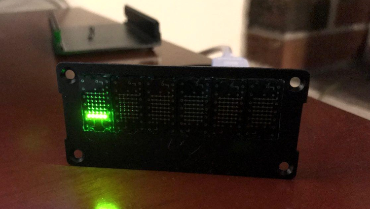
You should now see a solid line on the first display.
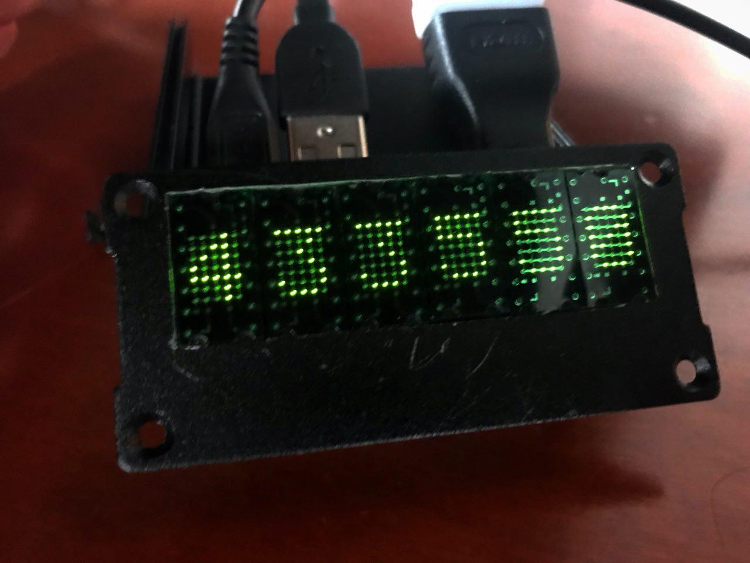
As for finding some fonts, I just grabbed font.py from the pimoroni/microdot-phat repo on GitHub, then wrote a script to convert it to font.h.
The problem with the microdot pHAT is that every other display; that is, matrix 2, is flipped 90°. Which means we're gonna have to do some calculations for each character.
#define MDH_ADR 0x61
#define CMD_MATRIX1 0x01
#define CMD_MATRIX2 0x0e

__u8
i2c_adr(__u8 addr) {
    return ioctl(d, I2C_SLAVE, addr);
}

void
printchar(int x, int chr) {
    int i, y;
    char buf[7], reg;

    reg = x % 2 ? CMD_MATRIX2 : CMD_MATRIX1;

    i2c_adr(MDH_ADR + x / 2);

    if (x % 2) {
        for (i = 0, y = 7; i < 7; i++, y--)
            buf[i] = 0;

        /* flip */
        for (i = 0; i < 8; i++)
            for (y = 0; y < 7; y++)
                buf[i] |= font[chr][y] & (1 << i) ? 1 << y : 0;

        for (i = 0; i < 7; i++)
            i2c_set(reg + i, buf[i]);
    } else
        for (i = 0; i < 7; i++)
            i2c_set(reg + i, font[chr][i]);
}
I've made a repo for all of the code.